Aurix: Generic timer module(GTM)
- Ashok Kumar Kumawat
- May 12
- 6 min read

The Generic Timer Module (GTM) is one of the most powerful and complex peripherals found in automotive microcontrollers, such as the Infineon AURIX™ family. Originally designed by Bosch, it is the industry standard for handling complex timing, engine management, and motor control tasks.
What is the use of the GTM?
The primary use of the GTM is to offload the main CPU (TriCore) from real-time, time-critical, and highly complex input/output tasks. Instead of the main CPU waiting for a timer to expire or an edge to arrive, the GTM handles it independently.
Input Capture: It can measure incoming signal periods, duty cycles, and detect edges with extreme precision.
Signal Generation: It can generate complex Pulse Width Modulation (PWM) signals for motor control or precise injection pulses for engines.
Angle/Time Domain: It can operate not just in the "time domain" (milliseconds) but also in the "angle domain" (degrees of engine rotation), which is crucial for internal combustion engines or electric vehicle motor commutation.
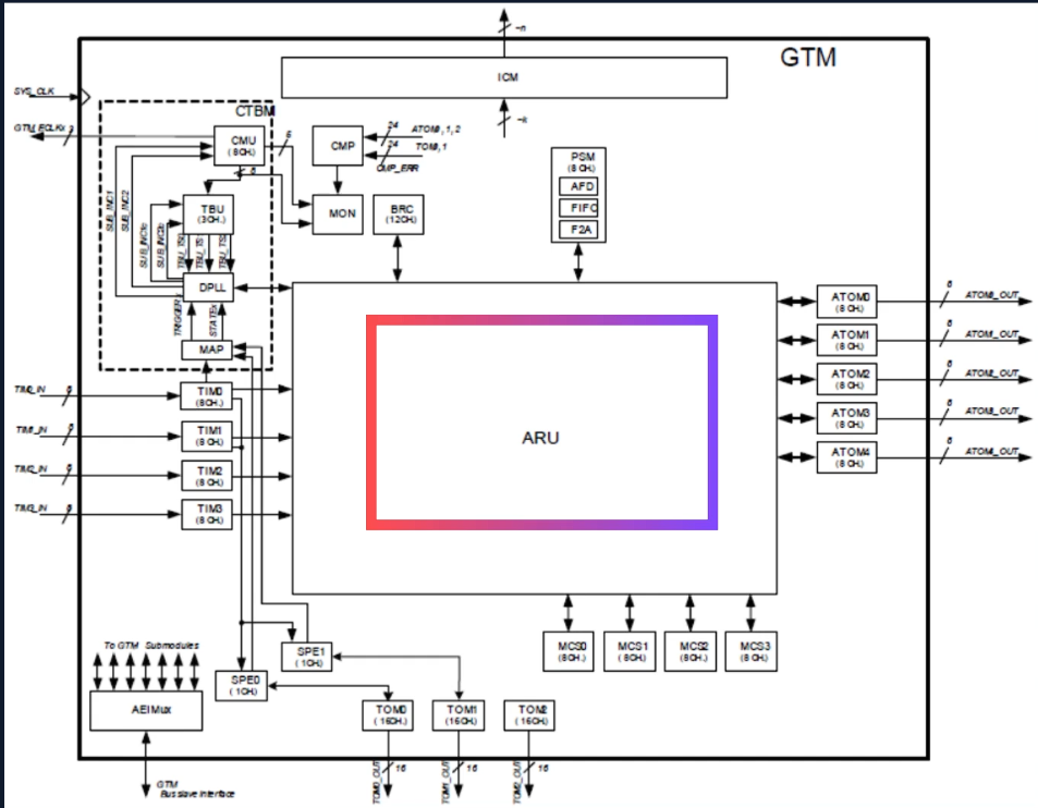
To understand the GTM, it is best to group its sub-modules by their actual functions within the system.
1. The Core Routing (The Heart of GTM)
ARU (Advanced Routing Unit): This is the massive, colorful block in the center of your diagram. The ARU is not a timer; it is a data routing network. It constantly and deterministically moves data (like captured timer values or new PWM duty cycles) between different sub-modules (e.g., from TIM to MCS, or from MCS to ATOM) entirely in hardware. This means data flows without any CPU intervention or bus delays. ARU Data Word - 53 bits Data0 - Duty Cycle
Data1 - Period ACB - Control bits

2. Input & Output Modules (The Interfaces)
TIM (Timer Input Module): This module handles incoming digital signals. It captures the timestamps of rising or falling edges, calculates periods and duty cycles, and filters out noise or glitches from external sensors.

TOM (Timer Output Module): This is your standard signal generator. It generates simple to moderately complex output signals, like standard PWM for driving LEDs, basic motors, or relays. It operates based on configurations set by the CPU.


ATOM (ARU-connected Timer Output Module): Think of this as an advanced TOM. The key difference is the "A" (ARU-connected). ATOM can receive its control data (like dynamically changing PWM duty cycles) directly from the ARU. This allows it to generate incredibly complex, rapidly changing signals on the fly, controlled by the internal MCS or DPLL, without bothering the main CPU.

3. Processing & Intelligence
MCS (Multi-Channel Sequencer): This is literally a small, programmable RISC processor embedded inside the GTM. You can write custom assembly code for the MCS to perform complex math, logic, and control loops on the timer data routed to it via the ARU. It acts as an autonomous brain for the GTM.

4. Clocks and Time Bases
CTBM (Complex Timer Background Module): This is an umbrella grouping in the architecture that contains the clocking and time-base modules (CMU, TBU, DPLL, MAP).
CMU (Clock Management Unit): Takes the main system clock and divides it down into various internal clocks used by all the other GTM sub-modules.

TBU (Time Base Unit): Provides the central "clocks on the wall" (counters) for the GTM. Other modules look at the TBU to know what time it is, or what angular position the system is at.

DPLL (Digital Phase Locked Loop): A highly specialized module primarily used in engine management. It takes physical signals from a crank/camshaft gear (which only has a few teeth) and "multiplies" them to provide a high-resolution, continuous angular position (e.g., down to 0.1 degrees of engine rotation).
MAP (Mapping Module): Acts as an interface that maps the incoming physical sensor signals (from TIM) into the DPLL for processing.
5. Infrastructure and Support Modules
PSM (Parameter Storage Module): A memory module connected to the ARU. It contains FIFOs (First-In-First-Out buffers) that can store a sequence of data points (like a complex PWM profile) and feed them to the ATOMs one by one. To understand why it's split into three parts, think of the PSM as a highly efficient waiting room for data. You need the waiting room itself, a door for people to enter, and a door for people to leave.
Here is the breakdown of those three sub-modules:
A. FIFO (First-In-First-Out)
What it is: This is the actual physical memory block (the "waiting room").
What it does: It stores arrays of data. You can configure these FIFOs to act as standard queues (where data is read once and disappears) or as Ring Buffers. In Ring Buffer mode, once the GTM reads the last piece of data, it loops back to the beginning.
Use Case: Storing a complex profile of 50 different PWM duty cycles and periods to create a specific electrical waveform for motor control or audio generation.
B. AFD (AEI to FIFO Data Interface)
What it is: The "Entry Door" from the main microcontroller. (AEI stands for the bus interface that the main TriCore CPU uses to talk to the GTM).
What it does: The AFD allows the main CPU (or a DMA controller) to write data into the FIFO, or read data out of it.
Use Case: When you first boot up your application, your main TriCore C-code uses the AFD to load those 50 different PWM duty cycles into the FIFO memory. Alternatively, if the GTM is capturing thousands of engine sensor timestamps, the AFD allows the main CPU to safely extract that logged data from the FIFO.
C. F2A (FIFO to ARU Data Interface)
What it is: The "Exit Door" to the GTM's internal routing network.
What it does: This module connects the FIFO directly to the ARU (Advanced Routing Unit). It listens for requests from other GTM modules (like the ATOM) and automatically hands them the next piece of data from the FIFO.
Use Case: An ATOM channel finishes its current PWM pulse and says to the ARU, "I need my next duty cycle." The F2A automatically grabs the next value from the FIFO and streams it over the ARU to the ATOM.
Putting it all together (The Real-World Superpower)
By combining these three sub-modules, you unlock one of the GTM's best features: Zero-CPU-Load Complex Waveform Generation.
Your main CPU uses the AFD to write a massive array of PWM parameters into the FIFO and sets it to Ring Buffer mode.
The main CPU then goes to sleep or focuses on high-level application logic.
Every time the ATOM finishes a PWM cycle, it asks the ARU for new instructions.
The F2A automatically pulls the next parameter from the FIFO and hands it to the ATOM.
The GTM generates a continuously shifting, highly complex electrical waveform infinitely—without ever interrupting the main TriCore CPU!
AEIMux (AEI Multiplexer): The bridge between the GTM and the rest of the microcontroller. The main CPU uses the AEI bus to read from and write to the GTM's configuration registers through this multiplexer.
ICM (Interrupt Control Module): Aggregates and manages all the interrupt signals generated by the various GTM sub-modules (like "capture complete" or "PWM cycle ended") and routes them to the main CPU.
SPE (Sensor Pattern Evaluation): Used specifically with the TOMs and TIMs to evaluate complex patterns from electric motor position sensors (like Hall sensors) to determine rotor position for BLDC (Brushless DC) motor control.
BRC (Broadcast): Because the ARU normally routes data point-to-point (one sender to one receiver), the BRC is used when you need to take one piece of data and broadcast it to multiple sub-modules simultaneously.

1 source can map to 22 destinations 12 Input Channels 22 Output Channels
CMP (Comparator) & MON (Monitor): Safety and diagnostic blocks. The MON ensures the internal clocks are running correctly, and the CMP can compare signals or data values to ensure the system is operating within safe, expected boundaries.
Summary of the Data Flow: A typical advanced workflow looks like this: A sensor signal enters the TIM -> The ARU routes that captured timestamp to the MCS -> The MCS calculates a new motor control response -> The ARU routes this new value to the ATOM -> The ATOM generates a new PWM output. All of this happens in the GTM, while the main TriCore CPU is completely free to run your application software.
Comments